Then add your design under test. The vast majority of vhdl designs uses clocked logic also known as synchronous logic or sequential logic.
Vhdl Code For Clock Divider Frequency Divider
All the designs which you want to test declare them as components in the testbench code.
Vhdl test bench clock. Vhdl component instantiantion failure entity or architecture wrong. If the clkgen procedure is placed in a separate package then reuse from test bench to test bench becomes straight forward. The basic building block of clocked logic is a component called the flip flop.
Clock divider is also known as frequency divider which divides the input clock frequency and produce output clock. In many test benches i see the following pattern for clock generation. Vhdl testbench creation using perl.
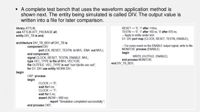
An entity and architecture. The time resolution is printed on the terminal for information using the concurrent assert last in the test bench. Given an entity declaration writing a testbench skeleton is a standard text manipulation procedure.
Vhdl code consist of clock and reset input divided clock as output. Declare all the inputs and outputs in the design to be tested. A test bench in vhdl consists of same two main parts of a normal vhdl design.
Make sure you initialize all the inputs to zero in the system. Proper clock generation for vhdl testbenches. Clock in testbench vhdl.
Endgroup jim lewis dec 15 15 at 1844. Ask question asked 4 years 1 month ago. Vhdl test bench dissected now is an excellent time to go over the parts of the vhdl test bench.
But in the case of sequential circuits we need clock and reset signals. Ask question asked 5 years 1 month ago. The clock rate data setup time and data hold times should be defined as generics or constants.
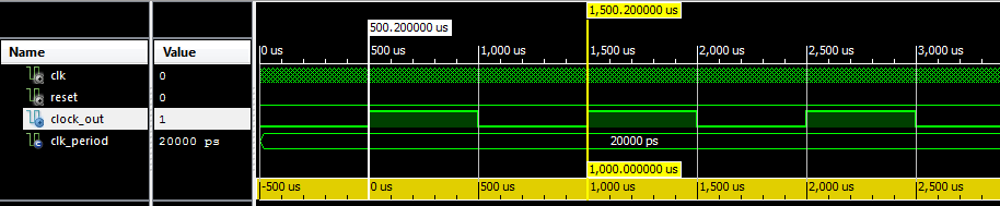
The clock process part in the code is only required for testing designs with a clock sequential designs. Process begin clk 0. In our case let us take input frequency as 50mhz and divide the clock frequency to generate 1khz output signal.
Hence test your clock first. Hardware engineers using vhdl often need to test rtl code using a testbench. Then add your waveform generation.
Testbench provide stimulus for design under test dut or unit under test uut to check the output result. Each one may take five to ten minutes. Waveform for clocks are shown in figure below.
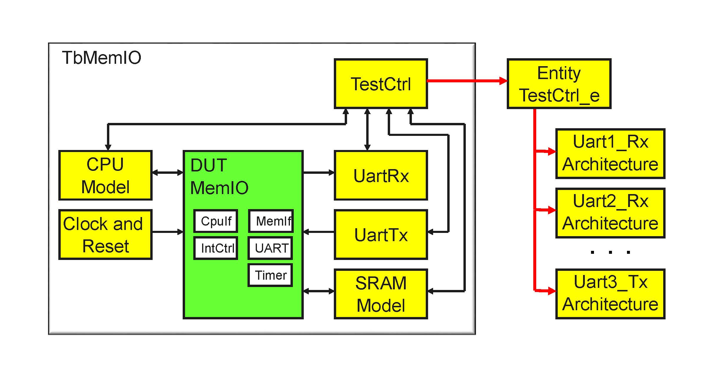
The entity is left blank because we are simply supplying inputs and observing the outputs to the design in test. Hence two additional blocks are required. Every design unit in a project needs a testbench.
Since clock is generated for complete simulation process therefore it is defined inside the separate process statement. A clocked process is triggered only by a master clock signal not when any of the other input signals change. Vhdl testbench is important part of vhdl design to check the functionality of design through simulation waveform.

How To Use A Procedure In Vhdl Vhdlwhiz

N Bit Gray Counter Using Vhdl

How To Use A Function In Vhdl Vhdlwhiz

Full Vhdl Code For Moore Fsm Sequence Detector Coding
Https Www Eng Auburn Edu Nelsovp Courses Elec4200 Slides Vhdl 206 20testbench Pdf

Electronics Blog Fpga Vhdl 8 Bit Datapath Testbench Structural Design

Electronics Blog Fpga Verilog Data Path Structural Design
Model Simulation Vhdl
Webinar Creating An Axi4 Lite Transaction Based Vhdl Testbench
No comments:
Post a Comment